
Generating schematics instead of drawing them
For a new large-scale dairy in Israel, JM Hardwarekonzepte GmbH did all the electrical planning with about 17,000 schematic pages.
JM Hardwarekonzepte GmbH in Büchen has concluded a demanding project: For a new large-scale dairy in Israel, the company did all the electrical planning with about 17,000 schematic pages. This task was made considerably easier by EPLAN Electric P8 and the schematic generator EEC One. As a service provider for plant engineering, JM Hardwarekonzepte GmbH in Büchen – about 50 km south-east of Hamburg – undertakes the electrical planning of process engineering systems. The projects range from dairies and systems for the food & beverage industry through to environmental simulation plants and tank systems for airports. Among the customers, with whom JM works continually, are GEA TDS GmbH of GEA Group AG, which is one of the leading plant engineers for the production of dairy products, fruit juices and raw materials for the food industry.
Large-scale project: New construction of a dairy
When GEA TDS was commissioned by Israeli company Central Bottling Co. (CBC) to carry out the planning and construction of a large-scale dairy in Netivot/Israel for end customer Tara, JM received an inquiry and then the order for the electrical planning. Managing director and company founder, Jürgen Möller says, “We were able to impress with an even larger reference project that we created with the Excel schematic generator, and with a cost-effective price because we work with a high degree of automation.”
Tight timescale – incorporation of existing devices
The particular challenge of this project was not just the scope of more than 15,000 schematic pages. The very tight timescale of four months and the incorporation of existing devices from the dairy’s other locations were also challenging. For this reason, a very precise structure was required for the electrical planning. The service technicians in charge attached great significance to being able to quickly find the right plan for the affected EI&C site in the event of a failure. For this reason, the JM planners created a sample schematic in accordance with EN 81346-1 with superordinate and simple function and location indicators. This distribution was made easier by a comparable structure in the process engineering plans of GEA TDS.
At the beginning: Creation of macros
In the first weeks after the order was received, there were still no released documents available. The electrical planners of JM used this time to create an EPLAN macro for every type of I&C location and to define the variables using EEC One. Jürgen Möller said, “It helped us here that GEA TDS was able to provide us with a plant BOM for all the EI&C, which we reduced down to the electrotechnically relevant entries and incorporated into EEC One. From this, we created the prerequisites for allocating the right macro to every EI&C location without any manual intervention.” In a similar manner, the planners searched for logical connections among the variables and automatically linked these in Excel, “A channel on a valve terminal always includes the same air connections, the PLC address offset and bit number. If the project is then structured so that a feedback inlet is allocated to each valve outlet, the dependencies for the input can be automatically matched to the valve terminal in relation to the channel.” All electrical planning macros for the dairy were structured in such a way that no manual adjustments were necessary afterwards. Only the safety shutdowns for the power cabinet required some slight reworking to consolidate signals into one cable, for example.
Planning in EEC One – Section by section
The main planning could then be completed by filling out the Excel lists. Jürgen Möller said, “To allocate the EI&C locations to the individual field cabinets and field bus systems using GEA TSD data and plans, we were able to obtain Branko Dimcevski who is an experienced external construction manager, who was incorporated initially into the planning and was then later responsible for the implementation on site. The countless filter functions of Excel made the planning work considerably easier for him.” So that the project could be handled in a linear structure, JM divided it into sections. When work was completed on one section, the relevant Excel file was passed on to the next workstation, at which the PLC start addresses, bus station numbers and reference designators were entered for the PLC. At another workstation, other Excel lists were adjusted for the actual field cabinet based on the utilisation and addressing determined in advance.
17,500 schematic pages
The actual creation of schematics took place on the fourth EEC One workstation. At another EPLAN workstation, the test runs were carried out and the field cabinets were finalised. The assembly of the power cabinets was not so easy as many more parameters had to be taken into account here. But at least the actual schematics of the drives could also be created with EEC One and the products and cable cross-sections could be added relating to the output. To simplify the control cabinet production, all field cabinets were mechanically identical and then equipped individually depending on the schematics. The 3D planning with EPLAN Pro Panel now provides additional security and precision. So that the production service provider receives customised schematics, the JM planners used the versatile filter options of EPLAN Electric P8. In total, the planning and documentation increased in this way to about 17,500 schematic pages. Jürgen Möller said, “To our knowledge, the project was never completely printed out. We provided the customer and the involved factories with the documentation electronically as PDF files and as a project file for EPLAN View using Dropbox.”
Insight and training from afar
During the installation in Israel, the planners in Büchen kept in close contact with the building site using Skype and “Team View”. Training for the assembly and maintenance personnel was also held in this way. In addition, there were two “loops” to ensure the documentation was up-to-date. Jürgen Möller said, “So that we did not overlook any changes, we compared GEA TDS’ old bills of material with the new bills of material using a comparison programme written especially for us. This allowed us to evaluate the changes and relocations and make adjustments where necessary. The construction manager of GEA TDS entered the changes that were carried out on the building site directly into the Excel lists. We then recreated the schematics with EEC One and sent them back.”
Follow-up project for plant expansion has already begun
The project was completed at the end of 2014 after the takeover of a number of used devices from other sites. And there are already follow-up projects: The JM planners have already been commissioned by GEA TDS to expand the plants. This was already taken into consideration during the initial planning phase. This shows how satisfied the plant manufacturer is with the work of JM Hardwarekonzepte. Jürgen Möller, in turn, is satisfied with the virtually flawless process of the extensive electrical planning work (see text box) – and with the CAD tools used, “Without EEC One, we would not have been able to accept this job or handle it.”
Figures relating to the scope of the planning project
| Entered pages | 12799 |
| Created evaluations | 4610 |
| Total number of pages | 17409 |
| Frequency converters | 309 |
| CPV10 valve terminal | 127 |
| Procentic Profibus hubs | 24 |
| ASI double master | 89 |
| Profibus PA master | 70 |
| Siemens S7 CPU 417 | 9 |
| File size of PDF | 149MB |
| E/A points transferred to Simatic software | 46958 |
| Periphery cabinets AE1016 | 82 |
| Power cabinets with double-sided fittings | 48.5 m |

The dairy has a high degree of automation. The electrical engineering is correspondingly laborious and extensive.
© GEA
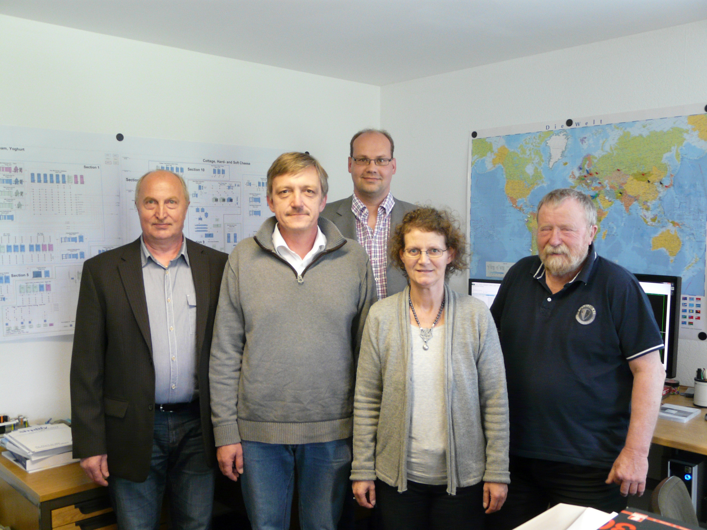
The team of JM Hardwarekonzepte GmbH. Second from left: Jürgen Möller, founder and managing director of the company.
© JM Hardwarekonzepte GmbH
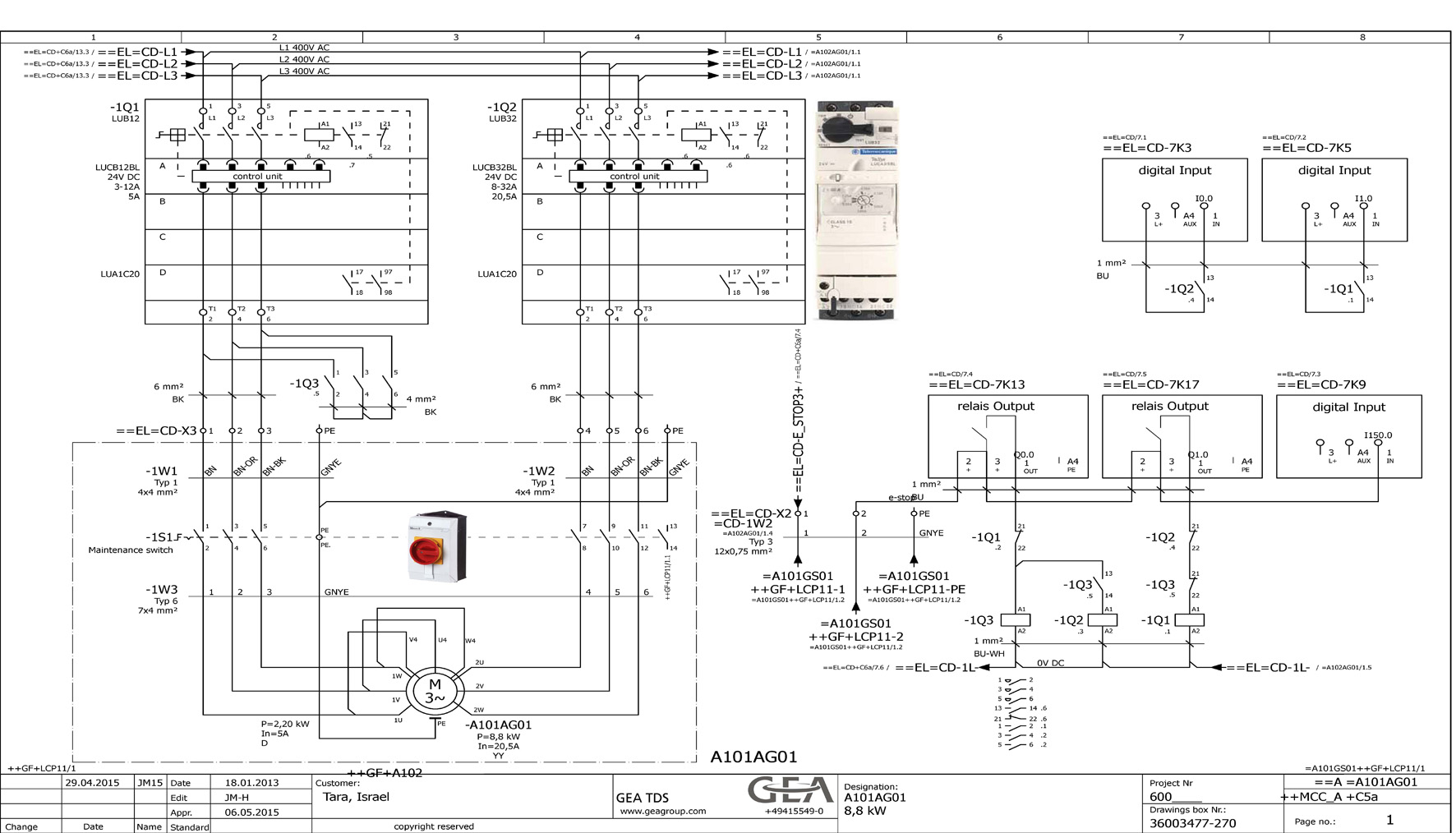
JM created about 17,000 schematic pages for the project. EEC One made this work considerably easier.
© JM Hardwarekonzepte GmbH
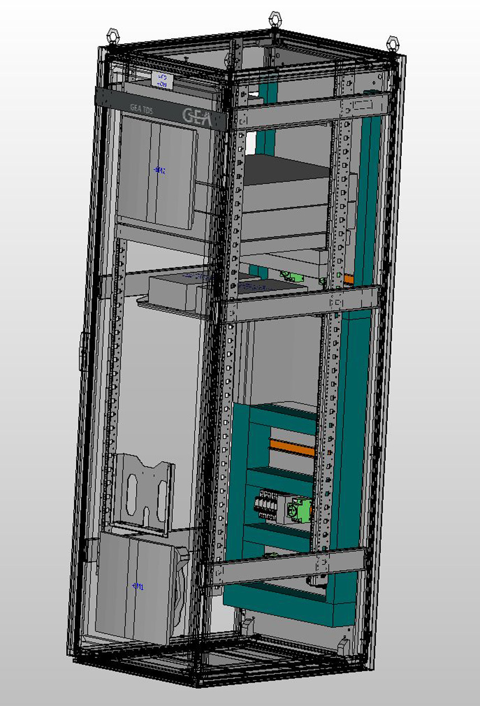
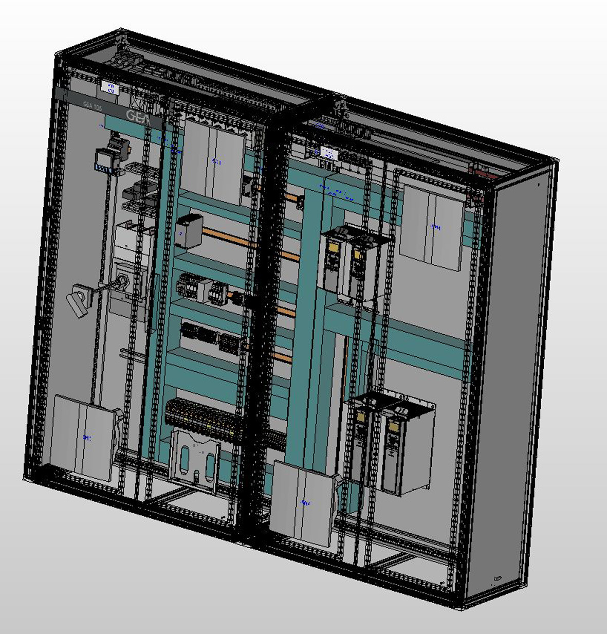
48 metres of control cabinet are needed to control the large-scale dairy.
© JM Hardwarekonzepte GmbH